If you decide to install your heat pump yourself, because all the heat pump installation estimates were too expensive, for example, then you may quickly need a heat pump installation diagram or even several air-to-water heat pump installation diagrams, in order to cross-check the information and manage to make a correct installation at home.
In this article, we will look at different resources that can help you find the right scheme to install your Air to Water heat pump.
Generally heat pump manufacturers are a good way to get free heat pump schematics to install. If you have some basic knowledge of heating or hydraulics, you will be able to understand and be inspired by them.
Grenelle Environnement air/water heat pump installation diagram
First, to have access to basic diagrams, for understanding and organization of the different hydraulic connections or other elements, you can consult the different cases of the Grenelle Environment diagram. It dates from 2013 but heating is not a world that evolves very quickly, and the hydraulic principles remain unchanged.
We will talk about the 4 most important ones:
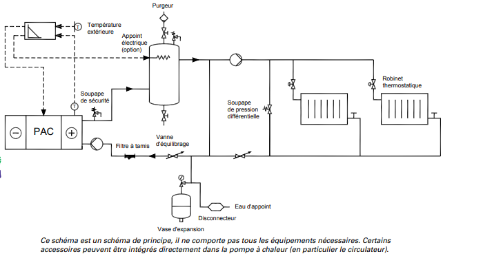
Heat pump with two-way buffer volume
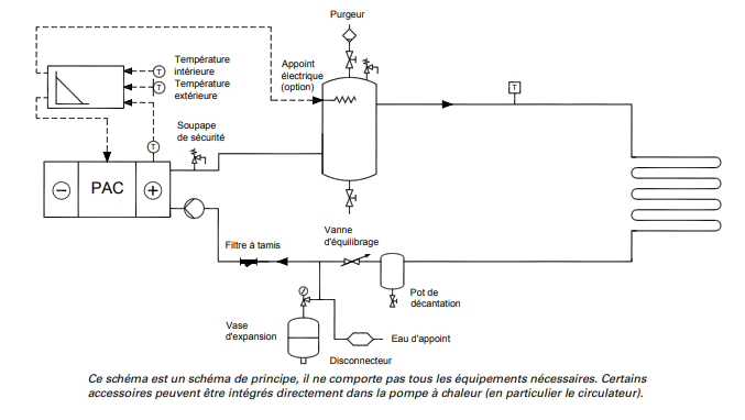
Well adapted to an underfloor heating circuit, we find all the elements necessary for the good hydraulic functioning of your heating installation by heat pump on underfloor heating. The buffer tank, which allows the heat pump to operate correctly, has two connections. This diagram is only valid if the emitters (hydraulic floor heating) are all the same. In this case, just an underfloor heating system (but not yet radiators with different temperatures)
To learn more about what happens in the buffer tanks, RAGE has also produced an interesting theoretical document to explain the physical hydraulic phenomena within these central elements of the hydraulic circuits in individual housing.
However, this assembly allows 2 taps to connect several hydraulic distribution circuits whose emitters are the same (example: two separate circuits of floor heating)
This is the scheme that should be considered
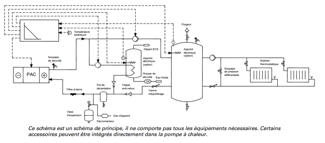
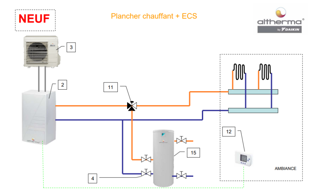
On the other hand, if you want to add the domestic hot water tank to your system, then here is the correct diagram (with one hydraulic circuit):
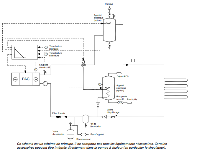
This was added to take into account the domestic hot water:
- Safety group
- Temperature sensor
- Electric resistance (in the tank)
- DHW tank
- 3-way valve with actuator, which passes either through the DHW tank or the buffer tank
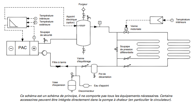
Heat pump with four-way buffer volume
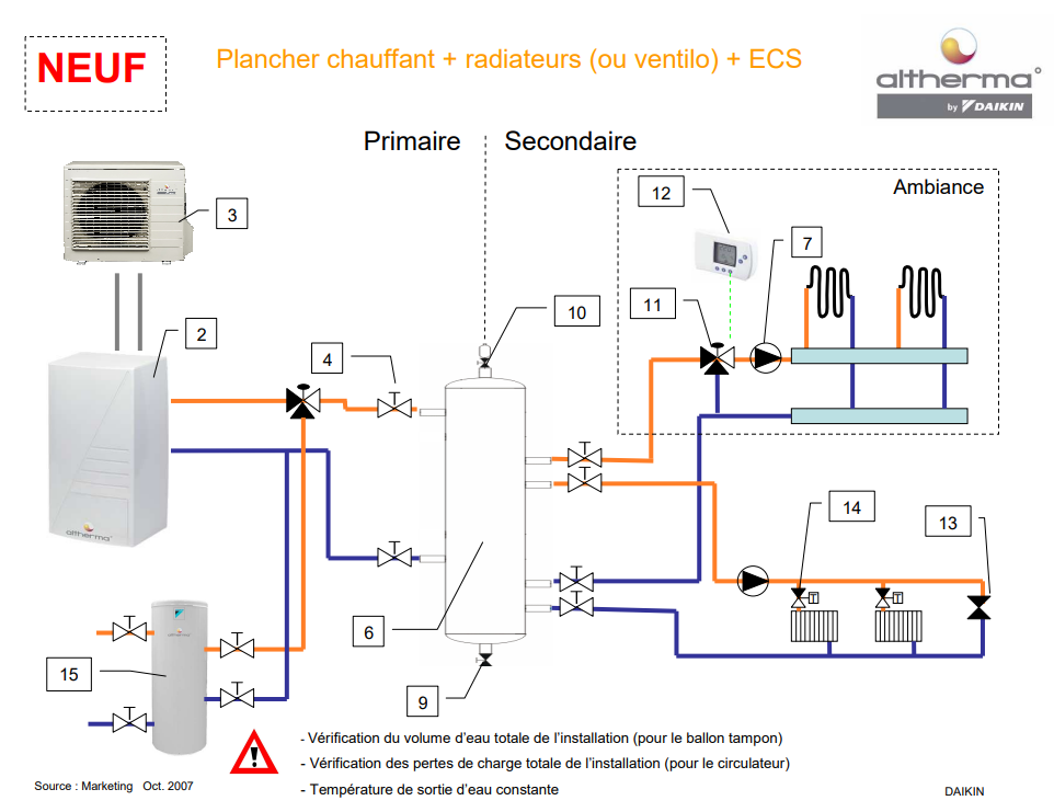
In this diagram we imagine an installation with hot water radiators. The 4-pipe system also makes it possible to connect several circuits with different emitters and therefore different temperatures.
For more information on the physical phenomena inside a buffer tank, see the document linked above.
Typical diagram with ECS :
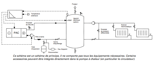
Heat pump with decoupling cylinder
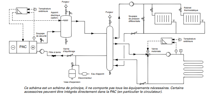
Diagram of an air-to-water heat pump installation with a decoupling cylinder. This is generally preferred if you are installing a heat pump on several hydraulic circuits with different emitters and temperature levels. Ex: Radiators 55°C and floor 40°C.
The role of the decoupling cylinder is to make the primary circuit independent from the secondary circuit.
In the context of this scheme, it is associated with a 2-pipe buffer tank whose role is to ensure a minimum volume of water for the homogeneous operation of the heat pump in order to avoid untimely compressor start-ups.
Interesting point: the decoupling cylinder can be replaced by a simple bypass: in this case the diagram would take the following form
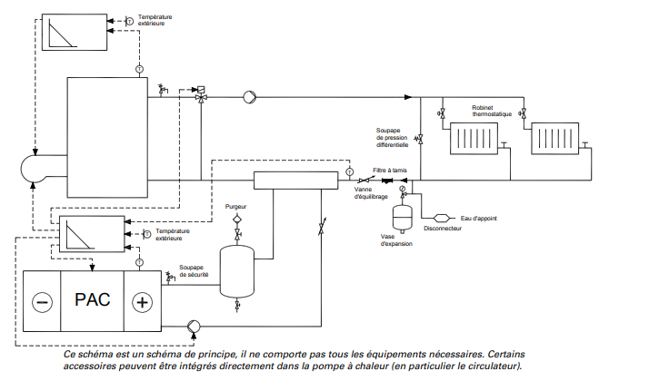
Heat pump with boiler as backup in simultaneous operation
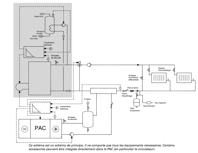
Finally, if you still want to keep your boiler in case the cold weather hits hard in your area, in order to avoid the use of an electric resistance that consumes too much energy, then you can consider this scheme.
In the case of radiators
And if we decide to add the production of domestic hot water, the diagram becomes :
You would like to have more information on the why and how of each element of the hydraulic circuit? Then consult the official RAGE Grenelle Environnement document by clicking on this link => Doc Air to water heat pump installation diagram
Diagram of the NiBE air/water heat pump installation
Europe's most powerful Swedish brand has a large database of heat pump designs to inspire you for your own installation.
Whether you have a F2120 with or without VVM or not, you can see the main elements of the circuit and get inspired by them. Moreover you can benefit from all the advice of connections rather intended for the professionals, via their documentations present on line.
I give you a technique to find a lot of them in Google. With this you should find your particular case. Enter the following command in google: site:nibe.eu filetype:pdf hydraulic
If you also want to have the other languages than French, remove the word "hydraulic".
You will find docs in this genreand many others.
Atlantic heat pump installation diagram
One of the best known heat pumps is certainly the Atlantic Alfea Duo. Its hydraulic diagram is also interesting to consult.
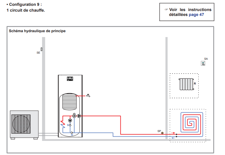
Case 1 heating circuit
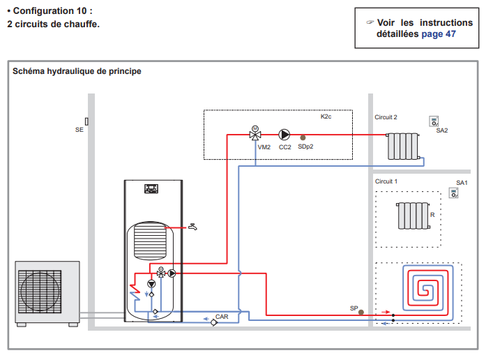
Case 2 heating circuits
Link to the Atlantic Alfea Duo insallation doc
Daikin heat pump installation diagram
Daikin is the star of heat pumps in France, even though it is a Japanese brand. The fact is that most installers like to work with this brand and especially with the Daikin Altherma 3H HT because it is quite affordable for individuals and therefore sells very well, it has a great design, it is well thought out to save time during installation thanks to the connections on top of the unit.
Daikin heat pump + underfloor heating installation diagram
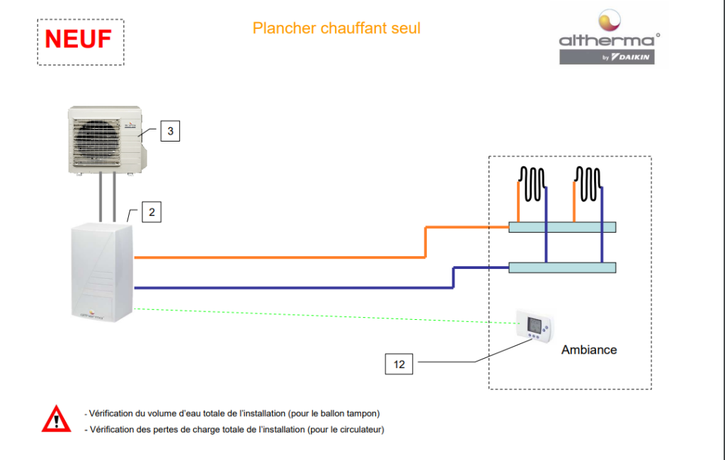
Source : http://www.pacenr.free.fr/
Daikin heat pump installation diagram + underfloor heating +ECS
Daikin heat pump installation diagram + underfloor heating + radiators + DHW
To see all the variants of the Daikin schemes you can consult this document on our server.
Heat pump installation diagrams by French heat pump manufacturer SDEEC
The French heat pump manufacturer has a nice doc with small hydraulic diagrams that can inspire you to do some clean work at home on your heat pump installation, or if you want to check the work of your installer or try to tinker with your heat pump (although this is not recommended, but you may be in a situation that leaves you no choice but to do it yourself)
Below is an example of a hydraulic installation diagram high-temperature heat pump type daikin altherma 3 h ht, 2 zones with DHW or instantaneous DHW
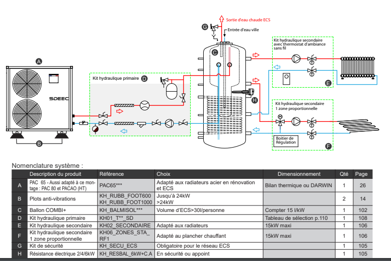
Moreover I leave you the link to the original documentation of the manufacturer which contains the numerous hydraulic diagrams => click here for your air water heat pump installation diagrams
Read more about heat pump installation :
Installing a heat pump by yourself
How far is the heat pump from the wall?

Julien G.
Juliena mechanical engineering graduate and specialist in climate engineering since 2009, has become a writer specializing in renewable energies, with expertise in heat pumps and photovoltaic solar panels for individual housing.
See all articles by this author